| Info |
|---|
Depending on the configuration and following revisions, the features of the board are subject to change. For detailed information on hardware specifications, please visit www.seco.com |
INDEX
| Table of Contents | ||
|---|---|---|
|
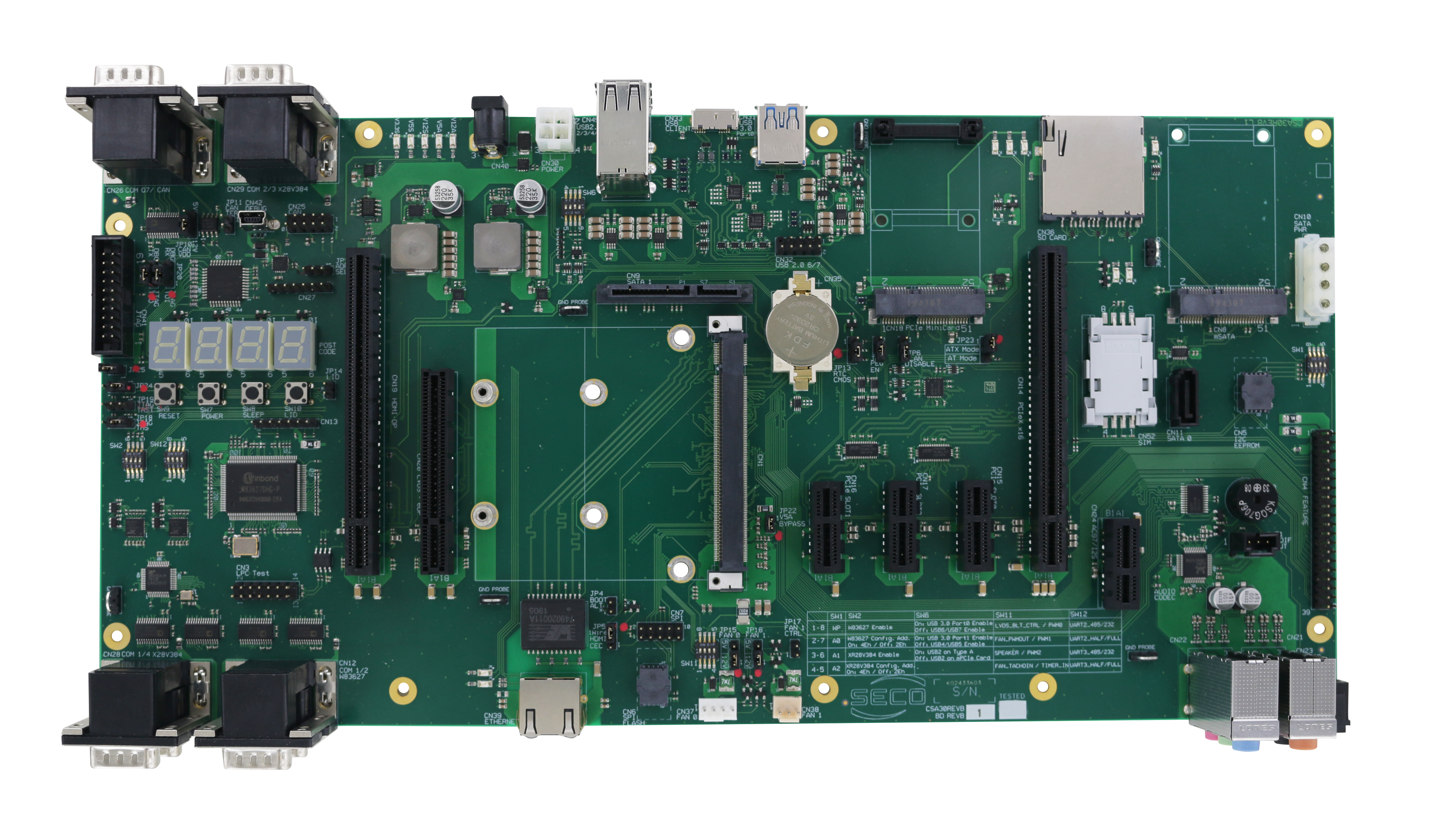
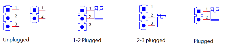
How can I configure jumpers?
Component | Description | Use | Default configuration (Fig.1) |
|---|---|---|---|
JP10 | CAN_VDD | Set jumper 1-2 for 12V CAN_VDD | 1-2 Plugged |
JP11 | CAN_TERM | No jumper for no termination | Plugged |
JP21 | JTAG TD0 | Set jumper 1-2 for JTAG debug | 2-3 Plugged |
JP20 | JTAG TD1 | Set jumper 1-2 for JTAG debug | 2-3 Plugged |
JP12 | ADR SEL | Set jumper 1-2 for 80/84h | 2-3 Plugged |
JP25 | Set no jumper for CN41-3 open Set jumper 1-2 for JTAG_TRST# on CN41-3 (JTAG Connector) | Plugged | |
JP24 | Set jumper 1-2 for RSTBTN# TO SRST# | 1-2 Plugged | |
JP19 | JTAG TRST | Set jumper 1-2 for JTAG_TRST# pulled-up | 1-2 Plugged |
JP18 | JTAG TMS | Set jumper 1-2 for JTAG_TMS pulled-up | 1-2 Plugged |
JP14 | LID | Set no jumper for normal operation | Unplugged |
JP4 | BOOT ALT | Set jumper 1-2 for boot from off module BIOS FLASH | Unplugged |
JP5 | Wire HDMI CEC | Set jumper 1-2 for 1-Wire BUS | 1-2 Plugged |
JP15 | FAN 0 | Set jumper 1-2 for 12V FAN | 1-2 Plugged |
JP16 | FAN 1 | Set jumper 1-2 for 12V FAN | 1-2 Plugged |
JP17 | FAN 1 CTRL | Set jumper 1-2 for FAN1 w/o control | Unplugged |
JP22 | V5A BYPASS | Set no jumper for AT no 5V_SBY mode | Plugged |
JP13 | RTC CMOS | Set jumper 1-2 for normal operation | 1-2 Plugged |
JP1 | PEG EN | Set no jumper for PCIe x1 | Unplugged |
JP6 | WLAN DISABLE | Set no jumper for RF operation allowed | Unplugged |
JP23 | ATX MODE/AT MODE | Set 1-2 for ATX PSU controlled | 1-2 Plugged |
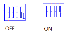
How can I configure micro switches?
Description | Default Configuration (Fig. 2) | |||
|---|---|---|---|---|
Position 1-8 | Position 2-7 | Position 3-6 | Position 4-5 | |
SW1 | OFF | OFF | OFF | OFF |
SW2 | OFF | OFF | ON | OFF |
SW6 | ON | OFF | ON | OFF |
SW11 | ON | ON | ON | ON |
SW12 | ON | ON | ON | ON |
What to connect and where?
Further information about placement and description of connectors are available here.
Accessories
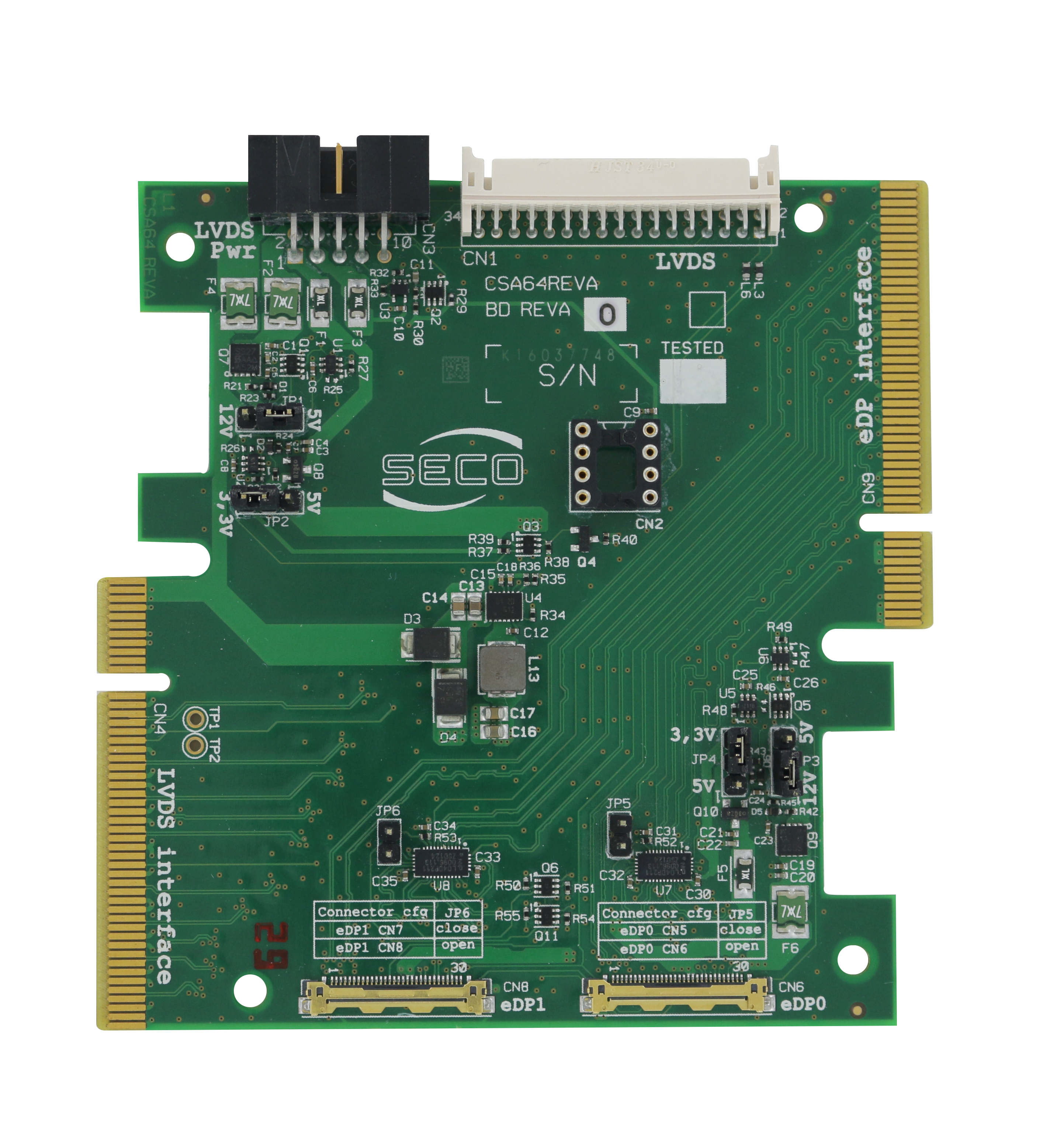
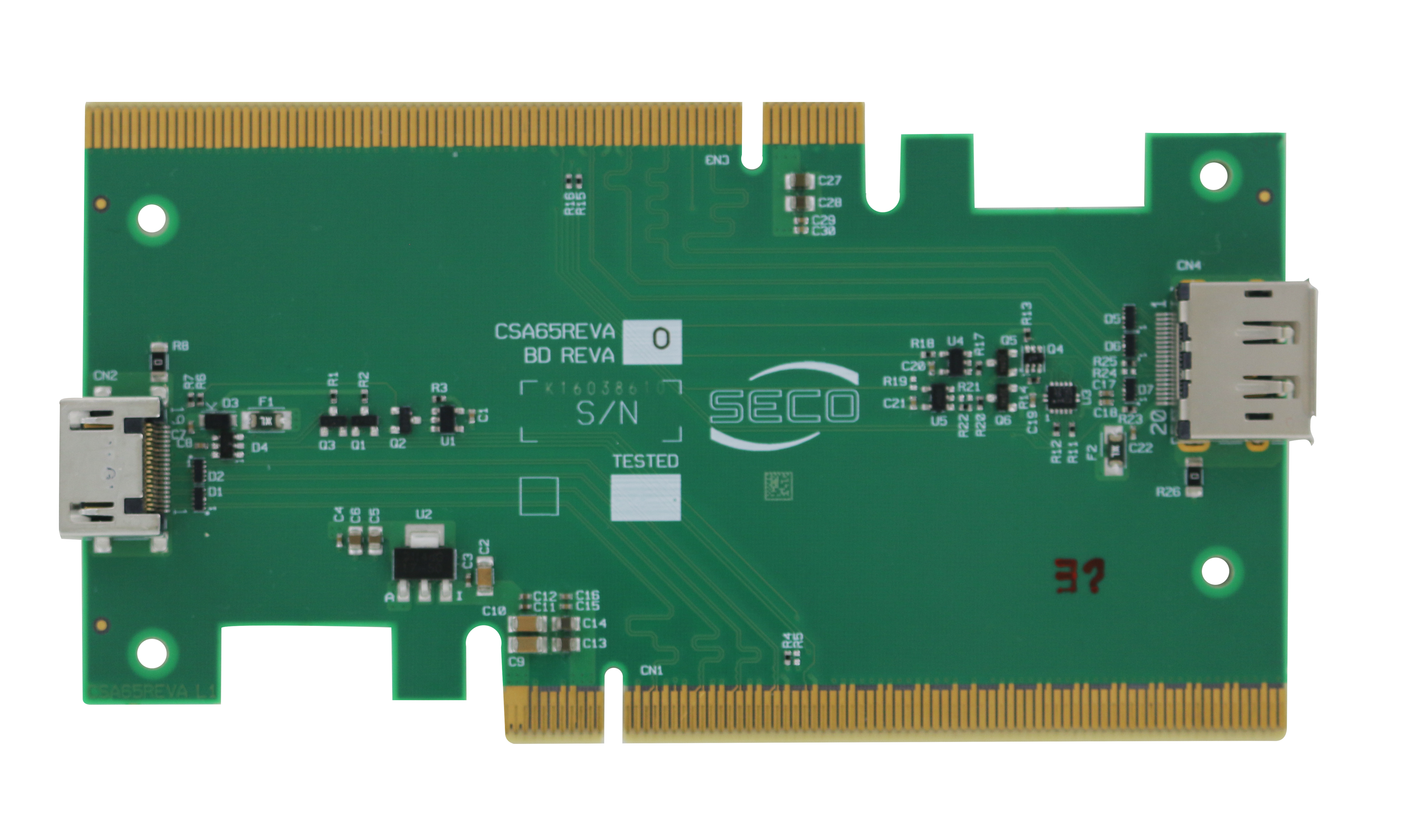
Fig. 3: VA64
Fig. 4: VA65
VA64 | ||
|---|---|---|
Component | Use | Default configuration (Fig.1) |
JP1 | Set jumper 1-2 for 12V backlight voltage Set jumper 2-3 for 5V backlight voltage | 1-2 Plugged |
JP2 | Set jumper 1-2 for 5V digital voltage | 2-3 Plugged |
JP6 | Set no jumper for 30p eDP connector | Unplugged |
JP5 | Set no jumper for 30p eDP connector | Unplugged |
JP3 | Set jumper 1-2 for 12V backlight voltage Set jumper 2-3 for 5V backlight voltage | 1-2 Plugged |
JP4 | Set jumper 1-2 for 5V digital voltage | 2-3 Plugged |