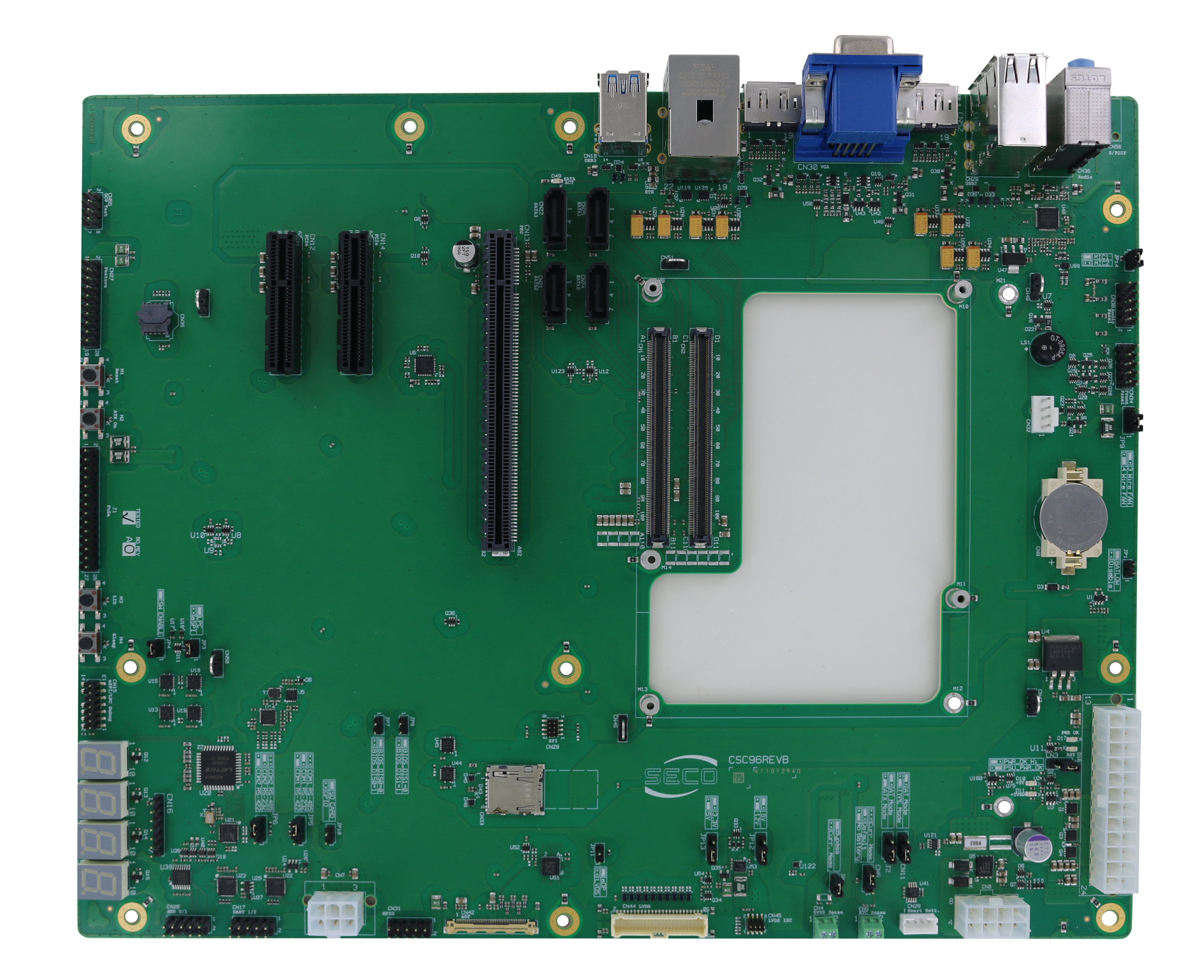
| Info |
|---|
Depending on the configuration and following revisions, the features of the board are subject to change. For detailed information on hardware specifications, please visit www.seco.com |
This carrier is contained in the development kit DEV-KIT-COMe-T6
INDEX
| Table of Contents | ||
|---|---|---|
|
How can I configure jumpers?
Component | Description | Use | Default configuration (Fig.1) |
|---|---|---|---|
CN11 | Set jumper 1-2 for TYPE mode Set jumper 2-3 for no TYPE/AT mode | 1-2 Plugged | |
J2 | Set jumper 1-2 for ATX mode | 1-2 Plugged | |
CN6 | Set jumper 1-2 for battery disconnected | 2-3 Plugged | |
JP2 | Set no jumper for | Plugged | |
JP12 | PANEL BACKLIGHT VOLTAGE SELECTION | Set jumper1-2 for 12V | 2-3 Plugged |
JP13 | PANEL VDD VOLTAGE SELECTION | Set jumper 1-2 for 5V | 2-3 Plugged |
JP11 | PANEL INTERFACE SELECTION | Set jumper for eDP | Unplugged |
JP8 | BIOS_DIS1 | Set JP8 and no JP7 for SPI on carrier | Unplugged |
JP7 | BIOS_DIS0 | Unplugged | |
JP10 | GPIO/SD | Set no jumper for GPIO | Plugged |
JP5 | COM1 | Set no jumper for RS-485 | Unplugged |
JP6 | COM2 | Set no jumper for RS-485 | Unplugged |
JP4 | ESPI/LPC# SELECTION | Set jumper for switch enabled | Plugged |
JP3 | ESPI/LPC# SELECTION | Set jumper for LPC from CEXP Set Set no jumper for ESPI from CEXP | Plugged |
JP14 | MIC#_SEL | Set no jumper for MIC2 | Plugged |
JP9 | 3-WIRES/4-WIRES FAN TACH DRIVER | Set jumper 1-2 for 4-wires fan | 1-2 Plugged |
JP1 | Set jumper for BATLOW# enabled | Unplugged | |
CN3 | Set jumper 1-2 for PSU PWR_OK | 1-2 Plugged |
What to connect and where?
Further information about placement and description of connectors are available here.

